Table of Contents
ToggleIntroduction
Battery powder sampling is a critical part of quality control throughout active material production, electrode manufacturing and battery recycling. Laboratory results can only describe the process material reliably when the collected sample is representative of the lot or material stream from which it was taken.
This requirement applies to materials with very different properties. LFP and NMC cathode powders may require careful control of contamination, moisture or atmospheric exposure. Fine graphite and silicon-based anode powders can present low bulk density, cohesion and inconsistent chamber filling. Black mass from battery recycling introduces additional challenges because its particle size, composition and density may vary considerably within the same material stream.
These differences mean that one sampling configuration cannot automatically be applied to every battery powder. Particle size distribution, flowability, segregation, sensitivity to the environment, required sample mass and process geometry must all be considered.
Sampling as an Integrated Process
Representative sampling also depends on more than the sampling valve itself. The sampling location, number and timing of increments, chamber filling, sample discharge, receiving container and laboratory preparation method are interconnected parts of the same sampling process.
ISO 11648-2 establishes general methods for sampling particulate bulk materials from moving streams and stationary situations, while ISO 14488 addresses the production of representative test samples for particle characterisation. These standards provide useful general principles, but each battery application still requires an engineering assessment based on the actual material and process.
This white paper examines the main challenges associated with four battery material groups:
- LFP Cathode Powders
- NMC and Nickel-Rich Cathode Powders
- Graphite and Silicon-Based Anode Powders
- Black Mass from Battery Recycling
It compares their sampling requirements and explains how sampling technology can be integrated into the process to improve representativeness, contamination control, containment, repeatability and sample recovery.
The purpose is not to define one universal solution, but to provide a structured method for selecting, positioning and validating a sampling system under representative operating conditions.
💡Engineering Insight
A sampling valve collects material, but the complete sampling process determines whether the resulting laboratory sample is truly representative.
Sources: International Organization for Standardization, ISO 11648-2:2001, confirmed in 2023, International Organization for Standardization, ISO 14488:2007, confirmed in 2023, International Energy Agency, Global EV Outlook 2026, 20 May 2026 and European Commission Joint Research Centre, Orefice et al., December 2024.
What Representative Battery Powder Sampling Means
A representative sample should reflect the relevant properties of the material stream or batch from which it is collected. This does not mean that every particle is identical. It means that the sampling method should avoid systematically favouring or excluding particular fractions of the material.
For battery powders, potential differences may involve:
- Particle Size
- Particle Shape
- Bulk Density
- Chemical Composition
- Moisture Content
- Surface Condition
- Fine and Coarse Fractions
- Foreign Particles or Impurities
These differences can become more pronounced during conveying, vibration, hopper filling or discharge. Fine and coarse particles may separate, while particles with different densities may follow different paths through the equipment.
A laboratory instrument can analyse the submitted sample with high precision, but it cannot correct a sample that was already unrepresentative when collected. Sampling must therefore be considered the first stage of the analytical process.
Increment, Composite Sample and Laboratory Sample
An increment is the quantity of material collected during one sampling operation. Several increments may be taken at defined moments or locations and combined to form a composite sample.
The composite sample may then be reduced or divided to produce the final laboratory sample. Each stage must preserve the relevant characteristics of the original material as far as practically possible.
The complete sequence is:
Process Material → Sampling Increments → Composite Sample → Laboratory Sample → Analytical Result
For a sufficiently homogeneous and stable process stream, one increment may sometimes provide useful information. For segregating or variable materials, several increments collected across the transfer or batch are generally required.
The number, timing and size of increments should be defined according to the material variability, batch size, process conditions and purpose of the analysis.
💡Engineering Insight
Analytical accuracy begins before the laboratory. If the collected increments do not represent the process material, greater laboratory precision will not make the final result representative.
Sources: International Organization for Standardization, ISO 11648-1:2003, confirmed in 2019, International Organization for Standardization, ISO 11648-2:2001, confirmed in 2023 and International Organization for Standardization, ISO 14488:2007, confirmed in 2023.
Material-Specific Sampling Challenges
Battery powders cannot be treated as one uniform material category. Their flow behaviour, sensitivity to the surrounding atmosphere, tendency to segregate and containment requirements vary according to their chemistry, particle properties and manufacturing stage.
LFP Cathode Powders
For LFP powders, the main sampling objective is often to obtain consistent increments without introducing contamination or favouring a particular particle fraction.
Sampling performance can be influenced by:
- Powder Segregation During Transfer
- Sampling Position
- Consistency of Chamber Filling
- Powder Retention
- Moisture and Contamination Limits
- Number and Timing of Increments
The required atmospheric protection must be defined from the material specification and process conditions. It should not be assumed to be identical for every LFP powder.
NMC and Nickel-Rich Cathode Powders
NMC powders require representative sampling together with careful control of environmental exposure. Research has shown that nickel-rich layered cathode materials can react with moisture and carbon dioxide in ambient air, creating surface compounds that may affect material performance.
The sampling system may therefore need to control:
- Exposure to Ambient Air
- Moisture Ingress
- Sample Container Sealing
- Cross-Contamination
- Powder Retention
- Operator Exposure
Sensitivity depends on the precise chemistry, nickel content, surface treatment and manufacturer’s specifications. The appropriate atmosphere must therefore be confirmed for each application.
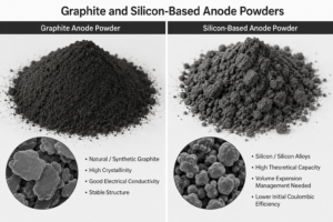
Graphite and Silicon-Based Anode Powders
Fine anode powders may present low bulk density, cohesion, electrostatic behaviour or limited flowability. Consequently, these properties can prevent consistent filling and discharge of a volumetric sampling chamber.
Accordingly, the main challenges may include:
- Bridging Above the Chamber Opening
- Incomplete Chamber Filling
- Powder Adhesion to Internal Surfaces
- Compaction During Piston Movement
- Incomplete Discharge
- Dust Formation
A larger chamber does not automatically solve these problems. Sampling reliability depends primarily on whether the material can enter and leave the chamber consistently.
Black Mass from Battery Recycling
Black mass can contain cathode material, graphite, lithium compounds, conductive additives and residual metallic or polymer fractions. As a result, its composition and physical properties depend on the incoming batteries and the recycling process.
Accordingly, the principal sampling challenges include:
- Material Heterogeneity
- Separation of Fine and Coarse Fractions
- Differences in Particle Density
- Abrasive Behaviour
- Variable Chemical Composition
- Dust Containment
Several increments collected across the material transfer may be necessary to represent this variability. One sample taken from the surface of a container should not automatically be considered representative of the complete batch.
Comparison of the Four Material Groups
| Material Group | Principal Sampling Concern | Important Process Consideration |
|---|---|---|
| LFP Cathode Powder | Representative Increments and Contamination Control | Sampling Location and Consistent Chamber Filling |
| NMC and Nickel-Rich Powder | Sample Integrity and Environmental Exposure | Moisture, Air Protection and Sealed Recovery |
| Graphite and Silicon-Based Powder | Poor Flow and Incomplete Discharge | Chamber Access, Orientation and Powder Retention |
| Black Mass | Heterogeneity and Segregation | Multiple Increments and Wear Control |
This comparison identifies the dominant concern for each material group. It does not replace testing with the actual powder or a review of the complete process conditions.
💡Engineering Insight
The chemistry identifies the material family, but the actual powder behaviour and process conditions determine the sampling configuration.
Sources: Embleton et al., Small, 2023, Air- and Moisture Robust Surface Modification for Ni-Rich Layered Cathode Materials, Dong et al., Chinese Physics Letters, 2022, European Commission Joint Research Centre, Orefice et al., December 2024 and International Organization for Standardization, ISO 11648-2:2001, confirmed in 2023.
How Sampling Errors Develop
Sampling errors can occur before, during or after the valve cycle. A sampler may operate correctly from a mechanical perspective while still collecting material that does not represent the complete process stream.
Incorrect Sampling Location
Material located near a hopper wall, outlet or stagnant zone may differ from material moving through the centre of the process.
A suitable sampling point should provide access to material that is actively moving. The actual flow pattern must be assessed because equipment geometry can create preferential flow paths or stagnant regions.
Segregation During Handling
Particles may separate during conveying, vibration, hopper filling and discharge because of differences in size, shape or density.
If sampling occurs only at one moment, the collected material may contain a disproportionate quantity of one fraction. Several increments distributed across the transfer can reduce this risk.
Incomplete Chamber Filling
Cohesive or poorly flowing powders may bridge above the sampler opening or only partially enter the chamber.
As a result, a chamber with a defined nominal volume does not necessarily collect the same mass during every cycle.
Incomplete Sample Discharge
Powder may remain attached to the chamber, piston, discharge connection or receiving container.
This retained material can:
- Reduce the Collected Sample Mass
- Change the Proportion of Fine and Coarse Particles
- Contaminate the Following Sample
- Make Repeated Cycles Less Consistent
Sample Alteration
The sample may change after collection through exposure to moisture, ambient air, foreign particles or unsuitable contact materials.
For sensitive powders, the receiving system must preserve the sample until it reaches the laboratory.
Sample Handling and Reduction
A representative process sample can still lose its integrity during transfer, division or preparation for analysis.
The procedure should define how increments are combined, how the composite sample is divided and how the final laboratory sample is stored and transported.
| Source of Error | Possible Consequence | Control Measure |
|---|---|---|
| Stagnant Sampling Point | Localised Sample | Sample from Moving Material |
| Inadequate Timing | Overrepresentation of One Transfer Stage | Collect Multiple Increments |
| Incomplete Filling | Variable Sample Mass | Test Chamber Filling |
| Powder Retention | Loss and Cross-Contamination | Optimise Discharge and Cleaning |
| Environmental Exposure | Altered Sample Properties | Use Appropriate Sealing or Inerting |
| Incorrect Sample Reduction | Loss of Representativeness | Apply a Defined Preparation Procedure |
💡Engineering Insight
Reliable sampling requires control of the complete path from the process stream to the laboratory container, not only the movement of the sampling valve.
Sources: International Organization for Standardization, ISO 11648-1:2003, International Organization for Standardization, ISO 11648-2:2001 and International Organization for Standardization, ISO 14488:2007.
Selecting the Sampling Point
The sampling point should be selected according to the purpose of the analysis. A convenient installation position is not necessarily the position that provides the most representative sample.
Before selecting the location, the following question must be answered:
Which material or process stage must the laboratory result represent?
The answer may relate to an incoming raw material, a completed blending operation, material leaving a dryer, a finished batch or a recycling stream before downstream processing.
Typical Sampling Locations
| Sampling Objective | Possible Sampling Location | Main Consideration |
|---|---|---|
| Verify Incoming Material | During Unloading or Transfer | Variation Within the Delivery |
| Check Blend Uniformity | Blender Outlet | Segregation During Discharge |
| Check Material After Drying | Dryer Outlet | Moisture and Environmental Exposure |
| Verify Finished Powder | Before Container Filling | Representation of the Released Batch |
| Characterise Black Mass | After Separation or Sieving | Heterogeneity Across the Transfer |
| Monitor Continuous Production | Gravity Chute or Transfer Line | Timing and Frequency of Increments |
Sampling from Moving Material
Sampling during transfer generally provides the opportunity to collect increments at different moments. This is particularly useful when the material may vary across the batch.
The sampling system should be positioned where:
- Material Is Actively Moving
- Powder Can Reach the Sampling Chamber
- The Flow Is Not Restricted by a Stagnant Zone
- The Sample Can Discharge Reliably
- The Receiving Container Can Be Connected Safely
- Inspection and Maintenance Remain Possible
Hopper and Vessel Installations
A valve installed on a hopper or vessel wall may collect material only from the region immediately in front of the opening. Funnel flow, mass flow, wall friction and internal geometry can influence which material reaches that position.
The flow pattern should therefore be reviewed before assuming that a side-mounted sampling point represents the entire vessel.
Gravity Chutes and Transfer Lines
A gravity transfer line can provide access to moving powder. Depending on the chute geometry and material behaviour, a side-mounted chamber or an intrusive sampler extending into the flow may be evaluated.
The selected system must avoid creating an unacceptable restriction, accumulation point or cleaning difficulty inside the process.
Before Final Packaging
Sampling before filling drums, bags or other containers can provide increments from the finished material as it leaves the process.
When several containers form one batch, the sampling plan should define whether the result must represent:
- The Complete Batch
- Each Individual Container
- Defined Groups of Containers
- Specific Stages of the Filling Operation
💡Engineering Insight
The correct sampling point is determined by the material population that the analytical result is intended to represent.
Sources: International Organization for Standardization, ISO 11648-2:2001 and International Organization for Standardization, ISO 14488:2007.
Sampling Technologies and Configuration Options
The sampling technology must be selected according to the powder behaviour, process geometry, required increment size, containment level and operating method. No individual valve design can guarantee representativeness independently of its installation and sampling plan.
Flush-Mounted Piston Sampling Valve
A piston sampling valve can be installed on a vessel, hopper, dryer or transfer line. In the closed position, the piston separates the process from the sampling chamber.
FAMAT’s Expanding Piston Technology uses an internal expansion mechanism to seal the piston at the process interface without a product-contact O-ring. This design is intended to minimise product traps at the connection between the equipment and the sampler.
This configuration may be suitable when:
- The Powder Can Reach the Valve Opening
- A Defined Increment Volume Is Required
- Product Retention Must Be Limited
- The Valve Must Remain Closed Between Samples
- The Sample Must Be Recovered Without Opening the Process
The actual sample mass depends on the powder bulk density and the degree of chamber filling. Nominal chamber volume must therefore not be confused with guaranteed sample mass.
Intrusive Sampling
In a vertical gravity chute, an intrusive sampler can extend into the moving powder stream. This may provide better access to the material when a wall-mounted chamber would sample only the region near the chute surface.
An intrusive configuration may be considered when:
- Material Flows Vertically by Gravity
- The Powder Stream Does Not Consistently Reach the Wall
- Access to the Moving Stream Is Required
- The Internal Obstruction Remains Acceptable
- Cleaning and Inspection Can Be Performed
The insertion depth, chute dimensions and powder flow pattern must be reviewed for each installation.
Manual and Automated Operation
Manual actuation can be suitable for occasional sampling when an operator is present. Automated actuation allows sampling cycles to be triggered at defined intervals or process stages.
Automation can support:
- Consistent Sampling Frequency
- Multiple Increments Across a Batch
- Sampling During Defined Transfer Stages
- Reduced Dependence on Operator Timing
- Integration with the Process Control System
Automation improves repeatability of the valve cycle, but it does not independently confirm that each increment is representative. Chamber filling and discharge must still be validated.
Sample Receiving Systems
The receiving system must allow the powder to leave the sampling chamber while preserving sample integrity and controlling dust.
Possible solutions include:
- Full-Bore Sampling Bottles
- Sealed Stainless-Steel Containers
- Flexible Bags
- Continuous Liner Systems
- High-Containment Transfer Devices
- Enclosed Sampling Cabinets
The correct solution depends on the required sample quantity, powder hazard, atmospheric sensitivity and laboratory handling procedure.
A full-bore container can reduce retention caused by shoulders or narrow internal transitions. For hazardous or highly dispersible powders, a continuous liner or closed containment system may reduce direct operator contact during sample recovery.
Gas Purging and Discharge Assistance
A gas connection may be considered for inerting the sampling cavity, protecting a sensitive sample or assisting powder discharge.
Any gas-assisted function must be assessed carefully because it may:
- Alter the Sample Moisture Level
- Disperse Fine Particles
- Favour the Loss of a Particular Fraction
- Compact Powder in the Chamber
- Create Pressure or Dust Hazards
The gas type, pressure, flow rate, sequence and discharge route must be compatible with the powder and validated under representative conditions.
Technology Selection Summary
| Process Condition | Configuration to Evaluate |
|---|---|
| Vessel or Hopper with Powder at the Wall | Flush-Mounted Piston Valve |
| Vertical Gravity Chute | Intrusive Sampler |
| Occasional Operator Sampling | Manual Actuation |
| Multiple Timed Increments | Automated Actuation |
| Atmosphere-Sensitive Powder | Sealed Container and Controlled Gas Connection |
| Hazardous or Highly Dispersible Powder | Closed or High-Containment Recovery System |
| Poorly Flowing Powder | Short Discharge Path and Orientation Testing |
💡Engineering Insight
The sampler should be configured around the powder and process. The process should not be assumed to behave according to the nominal valve volume.
Sources: FAMAT Sampling, EPT® and Powder Sampling Technology, FAMAT Sampling Systems Portfolio, FAMAT 125S Security Sampling Valve, FAMAT Continuous Liner Solution and International Organization for Standardization, ISO 11648-2:2001.
Sample Integrity, Contamination and Containment
A battery powder sampling system may need to protect three different elements:
- The Sample from the Surrounding Environment
- The Process Material from External Contamination
- The Operator from Exposure to the Powder
These objectives are related, but they are not identical. Each must be evaluated separately during system design.
Protecting the Sample
Moisture, ambient air or foreign particles can alter the condition of some battery materials after collection. Nickel-rich NMC powders are particularly relevant because exposure to moisture and carbon dioxide can modify their surface chemistry.
Where environmental protection is required, the sampling system may include:
- A Sealed Receiving Container
- A Controlled Sampling Atmosphere
- Inert Gas Purging
- A Defined Transfer Sequence
- Limited Exposure During Laboratory Handling
The required conditions must be based on the powder specification. Inerting should not be added automatically if it changes the sample, disturbs fine particles or creates an unnecessary process complication.
Preventing Cross-Contamination
Retained powder from a previous cycle or batch can contaminate the following sample. Product may remain inside the chamber, around the piston or within the discharge connection.
Cross-contamination control may require:
- Minimal Product-Retention Areas
- A Short and Direct Discharge Path
- Inspection of Product-Contact Surfaces
- Cleaning Between Materials or Batches
- Purging or Rinsing When Compatible
- Verification of Cleaning Effectiveness
The acceptable level of residual material depends on the analytical purpose and the difference between consecutive products or batches.
Controlling Operator Exposure
Fine powders can become airborne during bottle connection, sample discharge or container removal. Define the required protection from the material safety data, occupational exposure limit and site risk assessment.
Possible containment measures include:
- Sealed Sampling Bottles
- Mechanically Interlocked Connections
- Continuous Liner Systems
- Closed Transfer Devices
- Enclosed Sampling Cabinets
- Local Extraction Where Appropriate
The containment solution must cover the complete recovery sequence, including connection, filling, disconnection, sealing and transport to the laboratory.
Dust and Electrostatic Considerations
Fine graphite, anode powders and some recycled fractions may generate dust or electrostatic effects during movement. The actual risk depends on the material properties, concentration, process atmosphere and installation.
Where applicable, the engineering review should consider:
- Grounding and Bonding
- Static-Dissipative Materials
- Ignition Source Control
- Dust Release During Discharge
- Area Classification
- Compatibility with the Site Explosion-Risk Assessment
Do not assign a dust explosion classification to a battery powder solely from its commercial name. Instead, use material-specific test data and the facility risk assessment.
Balancing Protection and Representativeness
Containment or inerting equipment must not prevent the powder from entering or leaving the sampling chamber correctly.
For example, excessive gas flow could remove fine particles from the sample, while a restrictive receiving connection could increase powder retention. Therefore, validate protection measures together with sampling performance.
💡Engineering Insight
A contained sample is not necessarily representative, and a representative sample is not necessarily contained. A successful system must achieve both objectives when the application requires them.
Sources: Embleton et al., Small, 2023, Dong et al., Chinese Physics Letters, 2022, FAMAT 125S Security Sampling Valve and FAMAT Continuous Liner Solution.
Increment Size, Frequency and Sample Mass
A representative sampling plan must define both the quantity collected during each cycle and the number of increments taken across the material stream or batch.
A single large sample is not automatically more representative than several smaller increments. If the material changes during transfer, one large sample still represents only the moment and location at which it was collected.
From Chamber Volume to Sample Mass
For a volumetric sampling chamber, the theoretical sample mass can be estimated from:
Sample mass = Chamber volume × Bulk density
For example, a 10 ml chamber filled with a powder having a bulk density of 0.4 g/ml would theoretically collect:
10 mL × 0.4 g/mL = 4 g
This calculation assumes complete and consistent filling. The actual mass may differ because of:
- Voids Inside the Chamber
- Powder Bridging
- Compaction
- Variable Aeration
- Material Retention
- Incomplete Discharge
Repeated weighing of collected increments is therefore necessary during testing.
Determining the Required Sample Quantity
Define the required laboratory quantity before selecting the chamber. It depends on:
- The Analytical Methods
- The Number of Tests
- The Required Repeat Analyses
- The Particle Size Distribution
- The Expected Material Variability
- The Sample Preparation Procedure
If the laboratory requires more material than one chamber cycle can provide, combine several increments rather than selecting an excessively large chamber.
Defining the Sampling Frequency
For batch transfer, collect increments near the beginning, at defined intervals and near the end. For continuous production, trigger cycles according to time, transferred mass or process events.
| Process Type | Possible Increment Strategy |
|---|---|
| Batch Discharge | Increments Distributed Across the Complete Transfer |
| Continuous Production | Increments at Defined Time or Mass Intervals |
| Container Filling | Increments Across Selected or Individual Containers |
| Variable Recycling Feed | More Frequent Increments During Material Changes |
| Process Investigation | Separate Analysis of Individual Increments |
Do not define the sampling frequency from the powder name alone. Instead, match it to the expected variability and the precision required from the final result.
Composite and Individual Samples
Combining increments can produce a composite sample representing the average condition of a batch. Analysing increments separately can reveal when variation occurred.
The sampling plan should therefore state whether the objective is to determine:
- The Average Batch Composition
- Variation During the Transfer
- Differences Between Containers
- A Specific Process Deviation
- Compliance of Each Individual Lot
💡Engineering Insight
Chamber volume determines how much material may be collected in one cycle. Sampling frequency determines how much of the batch history is represented.
Sources: International Organization for Standardization, ISO 11648-1:2003, International Organization for Standardization, ISO 11648-2:2001 and International Organization for Standardization, ISO 14488:2007.
Testing and Validation
Install a piston sampling valve on a vessel, hopper, dryer or transfer line. In the closed position, the piston separates the process from the sampling chamber.
FAMAT’s Expanding Piston Technology uses an internal expansion mechanism to seal the piston at the process interface without a product-contact O-ring. Therefore, it helps minimise product traps at the connection between the equipment and the sampler.
Material Characterisation
Before testing, review the available powder information, including:
- Particle Size Distribution
- Bulk and Tapped Density
- Flowability
- Moisture Sensitivity
- Cohesive or Abrasive Behaviour
- Operating Temperature and Pressure
- Occupational Exposure Information
- Electrostatic or Dust Hazard Data
When information is unavailable, document this limitation rather than replacing it with assumptions based on the material name.
Functional Testing
Initial testing should verify:
- Chamber Filling
- Complete Piston Movement
- Sample Discharge
- Container Connection and Removal
- Powder Retention
- Operation Over Repeated Cycles
- Cleaning and Inspection Access
Conduct testing using the proposed chamber, valve orientation, discharge connection and receiving container.
Sample Mass Repeatability
First, record the mass collected during consecutive cycles. However, large variations may indicate bridging, inconsistent filling, compaction or incomplete discharge.
A stable collected mass provides useful evidence of repeatable operation. Nevertheless, it does not by itself prove representativeness. Moreover, repeated samples can have similar masses while containing the same incorrect proportion of particle fractions.
Representativeness Assessment
Where practical, compare samples from different stages of the transfer with samples obtained through an appropriate reference procedure.
The assessment may include:
- Particle Size Distribution
- Chemical Composition
- Moisture Content
- Bulk Density
- Fine and Coarse Fraction Distribution
- Relevant Impurity Levels
Therefore, the project team must agree on the test method and acceptance criteria before validation begins.
Sample Integrity and Containment
In addition, testing of atmosphere-sensitive or hazardous powders should verify:
- Environmental Exposure During the Cycle
- Integrity of the Receiving Container
- Dust Release During Connection and Removal
- Effectiveness of Purging or Inerting
- Retained Material After Sampling
- Cleaning Between Batches
Evaluate containment and inerting functions without losing sight of chamber filling, discharge and sample composition.
Long-Term Performance
Abrasive powders or repeated cycling can change clearances, surface condition and sealing performance over time.
The validation and maintenance plan should define:
- Inspection Intervals
- Wear Criteria
- Seal and Piston Checks
- Cleaning Verification
- Preventive Maintenance
- Requalification After Significant Changes
Changes to the powder, process conditions, chamber size, installation orientation or sampling sequence may require reassessment.
💡Engineering Insight
Repeatable valve movement proves that the mechanism operates. Validation must prove that the complete system delivers samples suitable for the intended analytical decision.
Sources: International Organization for Standardization, ISO 11648-1:2003, International Organization for Standardization, ISO 11648-2:2001 and International Organization for Standardization, ISO 14488:2007.
Engineering Selection Framework
Select a battery powder sampling system through a structured review of the material, process and analytical objective.
Step 1: Define the Sampling Objective
Confirm what the sample must represent:
- An Incoming Delivery
- A Complete Production Batch
- A Specific Process Stage
- Material Leaving a Dryer or Blender
- Individual Filling Containers
- A Continuous Recycling Stream
Step 2: Characterise the Powder
Document the properties that may affect sampling:
- Chemistry
- Particle Size Distribution
- Bulk Density
- Flowability
- Cohesion
- Abrasiveness
- Moisture or Air Sensitivity
- Containment Requirements
Step 3: Review the Process Geometry
Identify where the material moves and where segregation or stagnant zones may occur.
The review should include:
- Vessel and Hopper Geometry
- Transfer Direction
- Flow Pattern
- Available Installation Space
- Operating Pressure and Temperature
- Cleaning and Maintenance Access
Step 4: Select the Sampling Technology
Choose the configuration according to the actual process conditions.
| Application Condition | Configuration to Evaluate |
|---|---|
| Powder Reaches a Vessel or Hopper Wall | Flush-Mounted Sampling Valve |
| Material Falls Through a Vertical Chute | Intrusive Sampler |
| Occasional Sampling | Manual Actuation |
| Multiple Defined Increments | Automated Actuation |
| Sensitive Material | Sealed Recovery and Controlled Atmosphere |
| Hazardous or Dusty Powder | High-Containment Receiving System |
Step 5: Define the Sampling Plan
Specify:
- Increment Volume
- Number of Increments
- Sampling Frequency
- Timing Across the Batch
- Composite or Individual Analysis
- Required Laboratory Sample Mass
- Sample Reduction and Storage Method
Step 6: Select the Receiving System
The receiving container should support complete discharge while protecting the sample, process and operator.
Review its design for:
- Internal Restrictions
- Powder Retention
- Sealing
- Atmospheric Protection
- Containment
- Laboratory Compatibility
Step 7: Test with the Actual Material
Testing should confirm chamber filling, collected mass, discharge, sample integrity, containment and cleaning.
Therefore, the project team should finalise the system only after comparing the results with predefined acceptance criteria.
Step 8: Monitor Performance
After commissioning, the sampling system should remain part of the process control strategy. Changes in powder formulation, particle properties, operating conditions or equipment configuration may affect sampling performance.
💡Engineering Insight
Selecting a sampling valve is one engineering decision. Creating a representative sampling process requires all eight steps to work together.
Sources: International Organization for Standardization, ISO 11648-1:2003, International Organization for Standardization, ISO 11648-2:2001, International Organization for Standardization, ISO 14488:2007 and FAMAT Sampling Systems Portfolio.
No single universal valve configuration or fixed sample quantity can deliver representative battery powder sampling. Instead, LFP, NMC, graphite, silicon-based materials and black mass present different combinations of flow behaviour, segregation, environmental sensitivity, abrasion and containment requirements.
Therefore, a reliable sampling system must connect five elements:
- The Analytical Objective
- The Material Properties
- The Sampling Location
- The Sampling Technology
- The Validation Procedure
However, each material group presents distinct sampling challenges. For LFP cathode powders, sampling location and representative increments may be central concerns. In addition, NMC and nickel-rich materials may require protection from moisture and ambient air. Fine graphite and silicon-based powders can create difficulties with chamber filling and discharge. Likewise, black mass may require multiple increments to account for material heterogeneity.
Therefore, treat the sampler, receiving container, operating sequence and laboratory preparation method as one integrated process.
Testing with the actual powder remains essential. Nominal chamber volume, successful valve movement or consistent sample mass cannot independently demonstrate that the collected sample represents the process material.
💡Engineering Insight
Representative sampling is achieved when the material, equipment, procedure and analytical objective have been evaluated and validated together.
Related Technical Application Notes
For detailed guidance on individual battery materials, see:
- Representative Sampling of LFP Cathode Powder
- Representative Sampling of NMC and Nickel-Rich Cathode Powders
- Representative Sampling of Graphite and Silicon-Based Anode Powders
- Representative Sampling of Black Mass in Battery Recycling
Discuss Your Battery Powder Sampling Application
FAMAT Sampling can review your application according to:
- Powder Characteristics
- Process Geometry
- Sampling Objective
- Required Sample Quantity
- Atmospheric Protection
- Containment Requirements
- Manual or Automated Operation
- Cleaning and Validation Requirements
Contact FAMAT Sampling to discuss your battery powder sampling application.